LUARI LTD
Home
Systems
icon
Technical LibraryAboutApplicationsRequest中文(CN)

ZW-F Insulating Glass UV Exposure Tester

Controlled UV Exposure Testing for Insulating Glass

UV Resistance Evaluation System for Insulating Glass

ZW-F combines controlled ultraviolet irradiation with a cooled contact surface to evaluate insulating glass for fogging, oil deposits and other visible contamination after exposure.

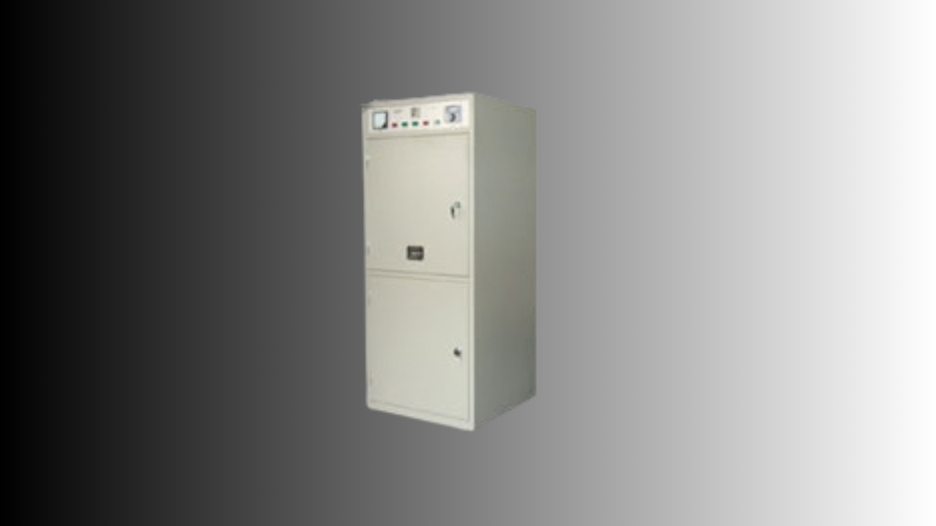
ZW-F insulating glass UV exposure tester
Chamber Temperature 50°C ± 3°C
Exposure Time 0–300 h
UV Source MLU 300 W

System Overview

UV Exposure and Cooled-Surface Evaluation

01

UV Exposure

Specimen is irradiated inside a closed test chamber.

02

Cooled Surface

A copper cooling plate is placed in close contact with the opposite side of the specimen.

03

Evaluation

Inspect for fogging, oil deposits or other visible contamination after UV exposure.

System Architecture

Core Test Components

  • UV irradiation chamber
  • MLU 300 W UV lamp
  • Copper cooling plate
  • Constant-temperature circulating water unit
  • Timing and temperature control

Test Principle

Evaluate Insulating Glass After UV Exposure

01

Controlled Irradiation

Place the insulating-glass specimen inside the closed test chamber and expose it to the UV source.

02

Surface Cooling

Maintain close contact between the opposite side of the specimen and the cooled copper plate.

03

Visual Evaluation

After exposure, inspect the cooled area for fogging, oil deposits or other visible contamination.

Key Features

Controlled Conditions for Insulating-Glass UV Evaluation

01

Controlled UV Exposure

Closed-chamber irradiation for insulating-glass evaluation.

02

Cooled Contact Surface

Copper cooling plate provides the cooled inspection area required by the test method.

03

Defined Chamber Temperature

Test chamber temperature: 50°C ± 3°C.

04

Controlled Cooling Water

Cooling plate inlet/outlet water temperature: 16°C ± 2°C.

05

Extended Test Duration

Programmable exposure time: 0–300 h.

06

Integrated Test Configuration

UV irradiation tester and constant-temperature circulating water unit form the complete system.

Technical Specifications

ZW-F Technical Data

Test chamber temperature
50°C ± 3°C
Power supply / power
AC 220 V / 1.8 kW
Cooling plate material
Copper
Light-source output power
>40 W/m²
Distance from specimen centre to light source
300 mm
Test light source
MLU-type UV lamp, 300 W
Cooling plate inlet/outlet water temperature
16°C ± 2°C
Time setting range
0–300 h
Operating ambient temperature
Not below 20°C
System configuration
UV irradiation tester + constant-temperature circulating water unit
Water supply requirement
No external water supply or drainage required

Test Workflow

Controlled UV Exposure Operation

  1. Prepare the insulating-glass specimen.
  2. Position the specimen inside the test chamber.
  3. Place the cooling plate in close contact with the opposite surface.
  4. Set the required test time and temperature.
  5. Start UV irradiation and cooling circulation.
  6. Complete the exposure period.
  7. Inspect the cooled area for fogging, oil deposits or other contamination.

Applications

Insulating-Glass UV Resistance Evaluation

  • Insulating glass units
  • IGU production quality control
  • Insulating-glass laboratories
  • Deep-processing glass manufacturers
  • Quality inspection laboratories

Discuss an Application

Review Your Insulating-Glass UV Exposure Requirement

Share your specimen type, test requirement and evaluation workflow. LUARI can review whether ZW-F is suitable for the intended insulating-glass application.